WaveForge · the buoy demonstrator · concept fixed 2026-09-17
Where This Is Going
Everything on this site so far is a board, a sensor or a bracket. This is the thing they are all parts of — the target for the next few months.
The demonstrator
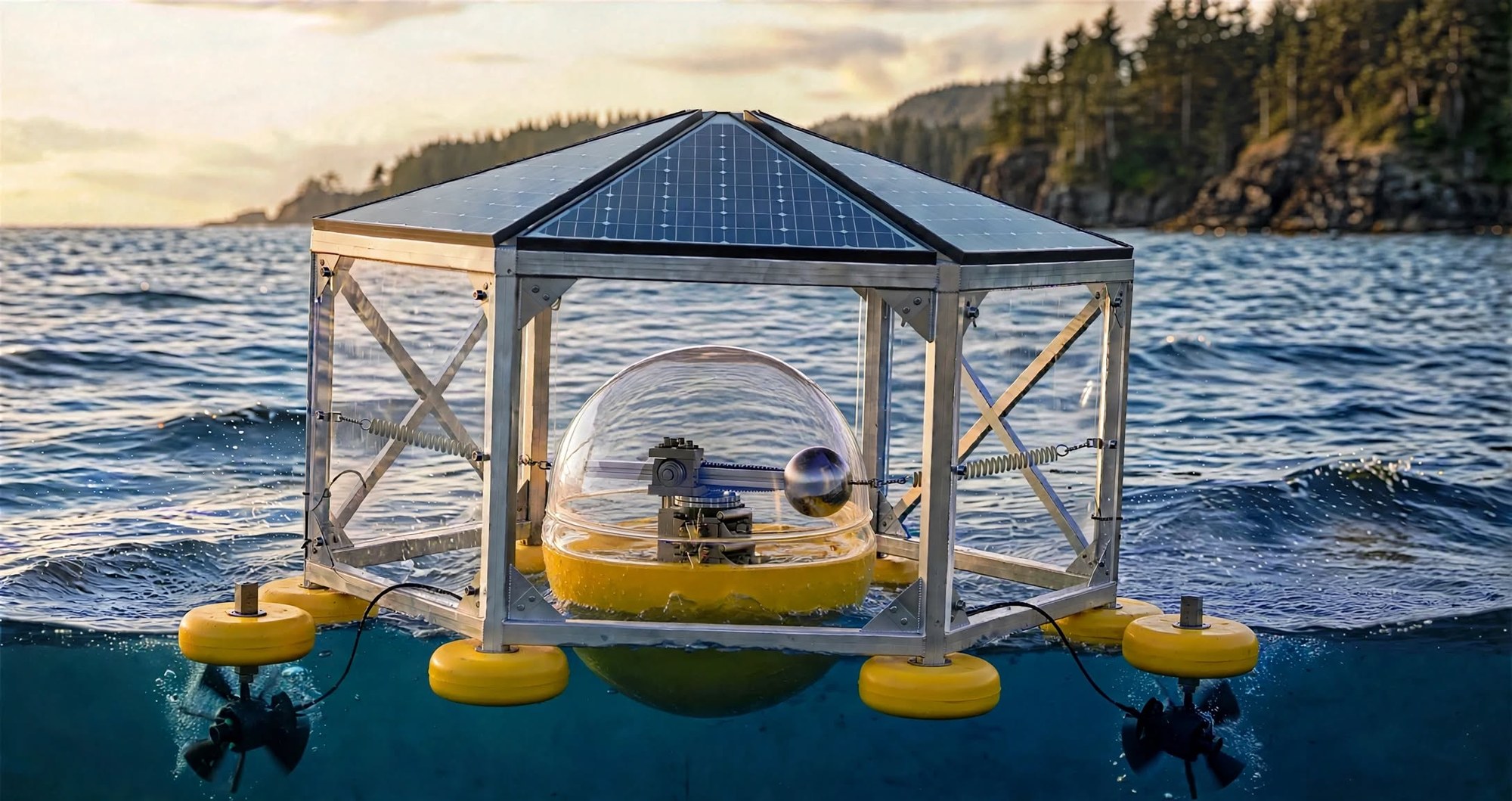
Ninth iteration, 2026-09-17. Six corner floats (small waterplane → quiet reference), inner sphere with a sealed dome and no rotary seal, thrusters submerged on outriggers, glazed bays, pitched solar roof.
Flotation upgrade — the fender ring
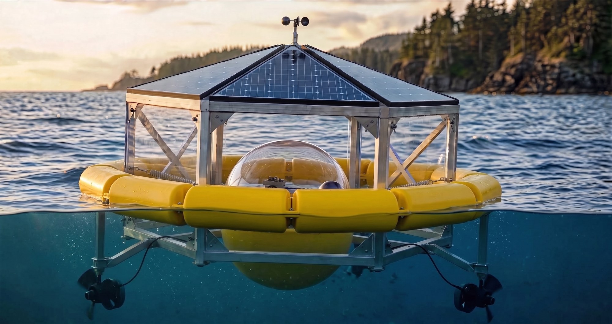
Why it is probably better. It is flotation and fender in one part. The ring stands proud of the frame on every face, so nothing — dock, boat, log, trailer — can strike the aluminum without hitting the float first. The frame’s corners, which are what would otherwise meet a dock, no longer exist as corners.
Segmented into six, one per bay, with bolted flanges. That keeps the frame modular and flat-packable, and a damaged segment is replaceable without rebuilding the float.
| Motion | What a big ring does | Does it matter? |
|---|---|---|
| Heave | Large waterplane → the frame follows the wave up and down strongly, where six small floats would not | Little. Frame heave relative to the inner body mostly just works the springs vertically. It is not what drives the mass. |
| Tilt | Wide footprint → the frame stays comparatively level while the small inner sphere follows the local wave slope and heels | Yes — this is the one. Relative tilt is the power input, so a tilt-stiff frame increases output. The ring may be the better choice for this machine, not merely an acceptable one. |
What it is
A buoy that converts the motion of a passing swell into electricity, and that can be tuned to the sea it is sitting in rather than being fixed at one response. Two bodies, sprung against each other.
- The inner body is free to rock. A sealed clear dome on a yellow torus float, carrying the whole mechanism, floating inside the frame and touching it only through springs. It is driven by tilt — so tilt freedom is the power input, and anything that stiffens it costs output directly.
- A vertical shaft carries an off-center mass. As the inner body heels to the swell, gravity gains a component in the mass’s plane and drives it around. Pitch and roll out of phase — which any real sea produces — keep it turning. The generator sits on the torus deck beneath it.
- ⭐ Nothing rotating passes through the enclosure. The shaft terminates inside the dome. Shaft, bearings, arm, rail, belt and generator are all sealed in together, so there is no rotary seal anywhere — the single most common leak path in a wave device simply does not exist here. The only penetration is a static cable gland.
- The mass rides a carriage on a rail, moved along the arm by a toothed belt. Out for a long lever and a slow swing, in for a fast one.
- The springs set the tilt period, which is the mode selector — the same four-spring principle, applied to a rotational mode instead of a translational one. ⭐ Their attachment height is the knob: at the body’s center of rotation they only center it and leave tilt free; above or below center they gain a moment arm and add tilt stiffness. Make the brackets height-adjustable and the period becomes something you can sweep.
- The frame is a braced hexagon carrying the springs, the two thrusters and a pitched solar roof. Everything structural lands on it, so no load reaches the inner body’s seal.
- Two thrusters on outriggers, hung well below the surface, turn the assembly to meet the swell square — rotate until pitch is greatest and roll least. No compass, no wave sensor. ⭐ Outboard mounting buys yaw authority: torque is thrust × radius, so the same thrust turns the buoy harder and costs less battery. They also pull clean water instead of the frame’s wake.
What got decided 2026-09-17
The concept went through four versions in an afternoon. Three real design decisions came out of it:
| Question | Answer | Why |
|---|---|---|
| How is the arm supported? | Two pillow blocks on one shaft, above and below the arm — not a tether from an overhead swivel | A tether only pulls, goes slack at the top of the swing and then snatches. Two bearings make the shaft simply supported. A single pillow block cannot do it — the insert is self-aligning by design and carries no bending moment. |
| Vertical shaft or horizontal? | Vertical | The shaft exits through the top of the dome, above the waterline. A horizontal shaft would penetrate the hull at the equator, at or below the waterline, where a rotary seal is a genuine leak path. Driven by hull tilt, not by heave. |
| Where do the thrusters go? | On outriggers, fully submerged | A thruster at the surface ventilates — it draws air down the duct and loses thrust, the failure his 2026-09-14 note called out (axis at least two duct widths under the working waterline). Hanging them below on outriggers fixes that and buys turning moment at the same time. |
| Does the shaft exit the enclosure? | No — it terminates inside | Kills the rotary seal entirely. Earlier versions ran the shaft up through the top to a bearing bracket, which needed one. Everything now lives inside the sealed dome and only a static cable gland leaves it. |
| One rigid body or two? | Two — inner body free to rock, sprung to the frame | A single rigid platform would work (that is essentially the Wello arrangement) but it throws away the sprung-mass tuning that the filings rest on. Two bodies keep spring rate as the mode selector. |
| How does power cross between the two bodies? | It doesn’t — two independent buses, ESP-NOW between them | Any cable spanning a body that rocks continuously is a fatigue failure waiting to happen. Generator and its pack inside the hull; solar, thrusters and their pack on the frame. ⭐ Side benefit: the solar bus and the wave bus are physically separate, so what the generator made can never be confused with what the sun made — C18 stays clean by construction. |
| How long can the arm be? | About 200 mm of radius | The sphere has to stay inside the sealed dome, so the dome’s diameter caps the arm. The 800 mm rail will be cut down. Costs torque, which scales with radius — but not the ratios this rig exists to measure. |
The honest part
The render shows a finished machine in open ocean at golden hour. Here is the actual state of it.
| Piece | State |
|---|---|
| Hull — two bowls, gasket, clamps | On hand and float-tested at the Willamette Park ramp, 2026-09-14. 8 lb per inch of immersion, ~70 lb of reserve. Gasket seeped at the end of the test — going to thicker neoprene and eight clamps. |
| Generator, gearbox, couplers, pillow blocks | On hand. The printed pillow-block housing was the one missing part. |
| Rail, carriage, stepper, belt | On hand. SBR20 rails and blocks, NEMA 17, GT2 kit. |
| Thrusters, sonar, lidar, MPUs, battery packs | On hand. |
| Control boards | Sensor hub working — seven halls and the MPU live through Blynk as of 2026-09-16. Stepper board v1.1 at the fab. |
| The frame | Not built. Not drawn either — no dimensions yet, only the concept above. |
| The clear dome | Does not exist. The real hull is opaque. A clear dome is right for a demonstrator because the mechanism should be visible; it is wrong for the ocean, where acrylic crazes, scratches and fouls. |
| Anything in the water producing power | Has not happened. No number on this page has been measured from this machine, because this machine does not exist yet. |
The dates
- 2026-09-30 — wave simulation on the bench. Sensors done, ten jumpers, first Z motion, steps per millimetre on Z only, open-loop replay from SD. Six-axis closed-loop control is explicitly not on the path; that is the trap.
- 2026-11-30 — the demonstrator characterized. Not “working” — characterized, which means curves: coast-down, output against load, output against wave input, and now a fourth, output against weight position. That last one is the tuning map, and it is the whole argument of the machine on one chart.
- A few months out — the thing in the picture. Frame built, hull sprung inside it, arm turning, thrusters holding heading, in water deep enough to matter.
Every part of it except the frame and the dome is already on the shelf. That is the point of the way this has been built — the expensive version of this machine was never ordered, it was accumulated.
Open — not yet decided
- ✅ RESOLVED 2026-09-17 — six floats at the frame’s corners, and the choice turns out
to matter more than "it needs to float."
⭐ A small waterplane makes the frame a QUIET REFERENCE. Wave force at the surface scales with the area
presented there — the principle behind spar buoys and semi-submersibles. So the two bodies end up with
exactly the right relationship: the inner sphere has a large waterplane and follows the wave (the mover),
the frame has a small one and stays comparatively still (the reference).
The difference between them IS the relative motion, and relative motion is the power.
Float sizing is therefore a design parameter to sweep, not just a load calculation.
Practical: size from a real weight estimate with reserve, then make them no bigger — six 300 mm discs half-submerged is only ~40–45 kg of buoyancy and the frame, glazing, solar and thrusters could eat most of it, so weigh parts as they arrive. And slim at the waterline, fat below: putting the volume deeper and piercing the surface with a narrower column makes the reference quieter still, and keeps flat discs out of the slam zone. - ✅ RESOLVED 2026-09-17 — the frame’s panels earn their place, for a reason I had missed. I had argued for deleting them since the inner dome does all the sealing. His argument is better: the inner body is the measuring instrument, and its tilt is the signal. Wind on the frame is a nuisance the thrusters absorb; wind on the inner body is contamination, because gusts are turbulent and cannot be separated from wave-driven motion after the fact. Shielding means the only thing touching the instrument is water — which is what C18 needs. They also stand between a knock and the brittle acrylic dome. ⭐ The arrangement that gets both: glaze the UPPER bays, leave the LOWER bays open. Wind lives above the water, slam lives at it — so panels where the wind is, open where the water is. Keeps the shielding and the protection, drops the wave-slam load case. ⚠️ Honest counter: panels raise the whole assembly’s sail area and its center, so more leeway and more overturning moment. The wide waterplane should carry it, but measure the heel angle in a stiff breeze before trusting a dataset taken in one.
- Brace the thruster outriggers. As drawn they are cantilevers crossing the waterline, which is the worst place for an unbraced member — that is where slam lands, cyclically, forever. A diagonal from each arm back to the frame’s upper ring turns bending into tension for the cost of one strut each.
- The thrusters are now the deepest thing on the buoy — first to touch bottom at a ramp, first to catch kelp or a stray line. Wants a skid or guard below each, and the draft number written down before launching anywhere shallow. Run the cables inside the struts, or clamped hard along the back edge; a cable hanging in the flow flutters and work-hardens at the gland.
- Bumpers. A body free to rock inside a fixed cage will touch it in any real sea, and acrylic against aluminum chips the acrylic. Generous clearance and soft replaceable bumpers on the frame’s inner faces, sized so the hull meets rubber before anything rigid.
- The sphere is steel in the render, and the generator sits directly beneath it. The no-steel-in-field rule applies — check with the magnetic viewing film once assembled; if the field reaches the swept circle it becomes lead or brass.
- Prior art search, before filing. An eccentric mass on a near-vertical axis driven by hull motion is an existing architecture — Wello’s Penguin is the first to check, ISWEC the related gyroscopic version. If the base architecture is prior art, the novelty sits in the within-cycle inertia modulation and the swell-group scheduling, not in the rotating mass.
Private build log · WaveForge / StabilityCore · concept render 2026-09-17